Quick answer
The short answer: Testing, visual inspection and packaging are the last chance to stop a defective inductor before it reaches a customer's pick-and-place machine. Specify three things: a complete electrical test set (inductance, DCR, Q, and where relevant saturation current), an inspection method that can see inside the part (UV-IR thermal imaging detects hidden cracks that optical inspection cannot), and a packaging stage whose cavity indexing accuracy matches the feeder tolerance of the customer's placement equipment.
Why the last stage decides your defect escape rate
Every process before this one has already added value to the part. Winding, gluing and soldering have all been paid for. If a defective inductor passes the final stage, you do not just ship a defect — you ship every upstream cost inside it, plus the cost of the customer's line stoppage when it fails.
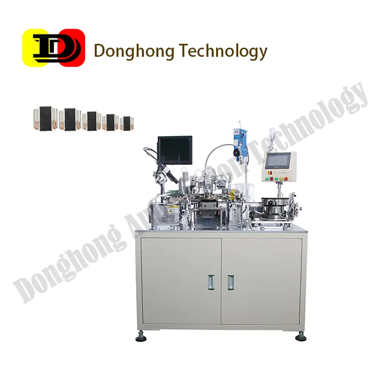
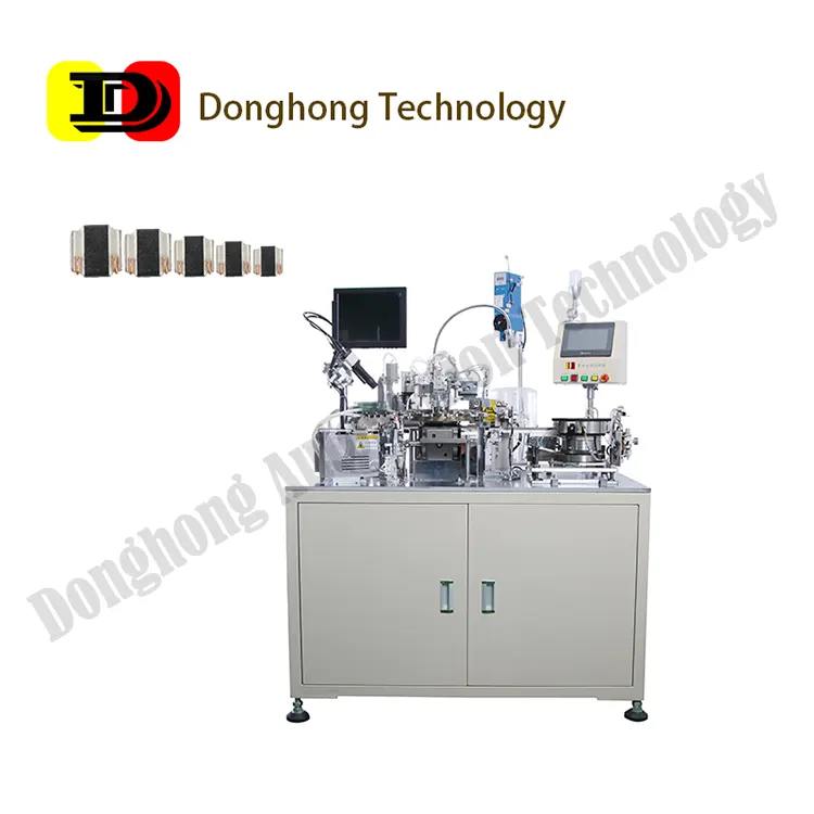
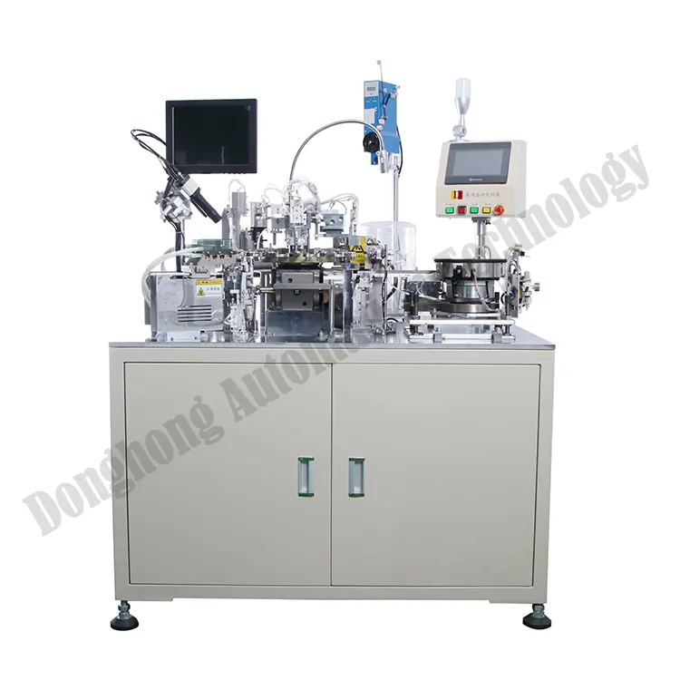
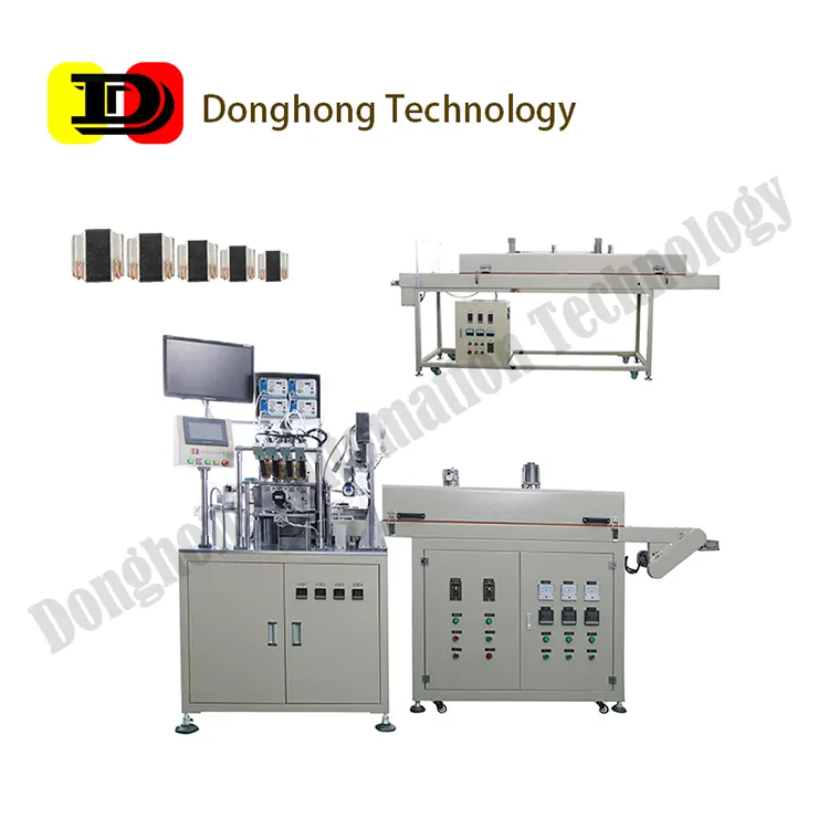
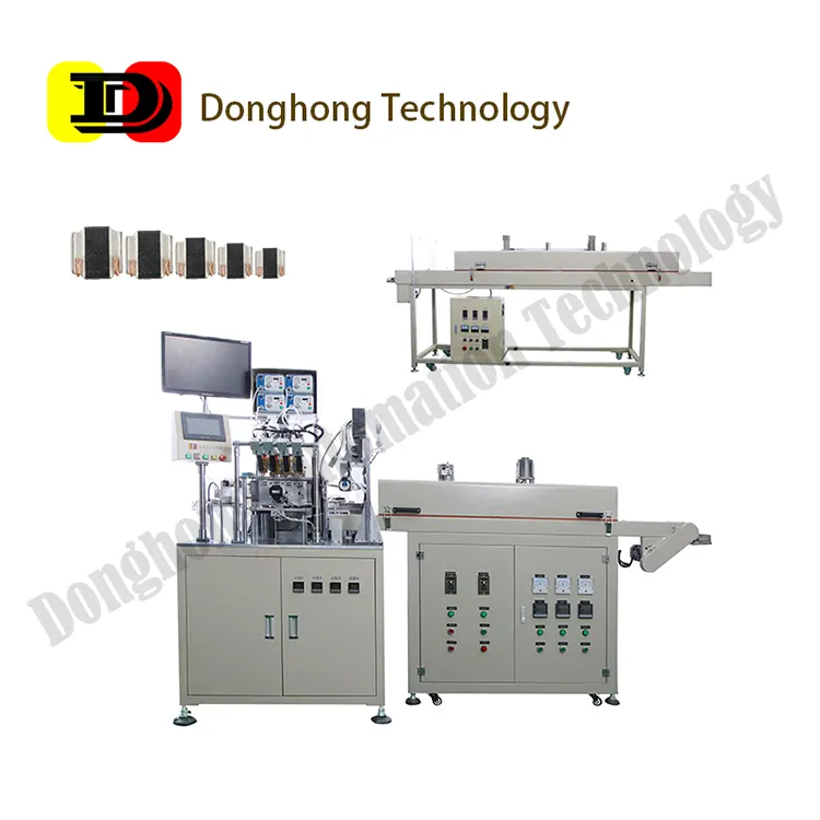
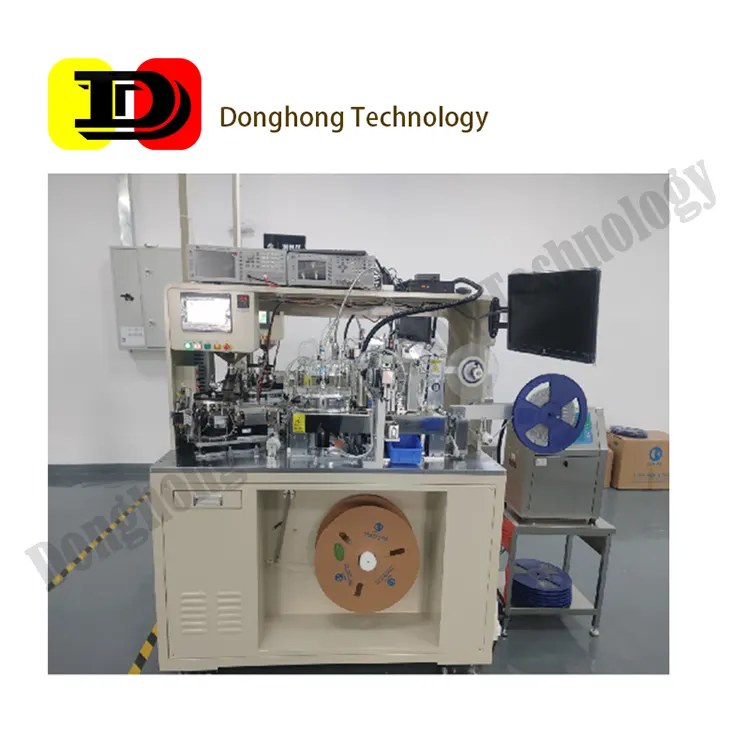
That asymmetry is why the test-and-pack stage deserves the same specification attention as the winding machine. It is also the stage where the widest range of machine architectures exists, from a simple electrical tester to an integrated platform combining electrical test, visual inspection, marking and tape-and-reel packaging in one pass.
The electrical test set: what must actually be measured
- Inductance (L) at the specified frequency. Inductance is frequency dependent. Testing at the wrong frequency produces a number that does not correlate with the customer's in-circuit measurement. The test frequency must match the application — typically 100 kHz or 1 MHz for power inductors, higher for RF parts.
- DC resistance (DCR). DCR directly affects efficiency in power conversion. It also serves as an indirect indicator of winding defects: an out-of-tolerance DCR usually means a wrong turn count or a partially broken strand.
- Quality factor (Q). For RF and high-frequency ceramic inductors, Q at the operating frequency is the parameter the customer's design depends on.
- Impedance and saturation behaviour for common mode and power inductors, where the part's function is suppression rather than energy storage.
A test machine that measures only inductance will pass parts that the customer rejects on DCR. Specify the full parameter set your finished part datasheet publishes — not a subset of it.
Hidden cracks and the limits of optical inspection
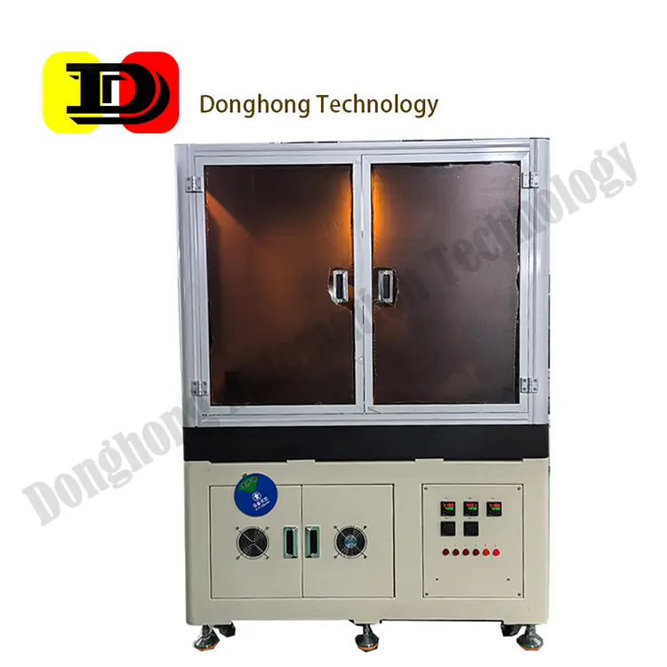
Chip inductors can carry defects that are physically invisible from the outside: cracks inside the magnetic core or beneath the coil substrate. These are sometimes called dark cracks. They arise from mechanical stress during molding, pressing or handling, and they do not change the external appearance of the part at all.
Conventional optical inspection equipment — cameras looking at the visible surface — cannot detect them, because visible light does not penetrate the core material. A part with a hidden crack may also pass electrical test at room temperature, because the crack has not yet propagated into the current path.
The failure appears later. During the customer's reflow process, thermal expansion opens the crack; in service, mechanical or thermal cycling propagates it. The result is inductance drift, an open circuit, or a short — and because the defect originated at your factory, the failure is attributed to your part even though it surfaced at the customer's line or in the field.
This is particularly consequential for high-reliability applications: automotive power supplies, fast-charging modules and communication base stations, where a single field failure carries disproportionate cost.
UV-IR thermal imaging: how it works and when to use it
Active thermal imaging overcomes the limitation that stops passive infrared inspection. Passive infrared relies on the part's own heat emission — at room temperature an inductor has essentially no temperature difference to image, and a crack generates no heat of its own.
An active method excites the part first (for example with UV or IR energy) and then images the thermal response. A crack interrupts heat conduction through the material, so the region around it heats and cools at a different rate from the surrounding solid. The thermal signature is what the camera detects — the defect becomes visible through the material, not on it.
Practically, this means UV-IR thermal imaging can be used as an in-process inspection stage for parts destined for high-reliability applications, and as an audit tool for verifying that molding and pressing parameters are under control. It does not replace electrical test: a crack that has not yet affected the current path passes electrical test, which is exactly the case this method is designed to catch.
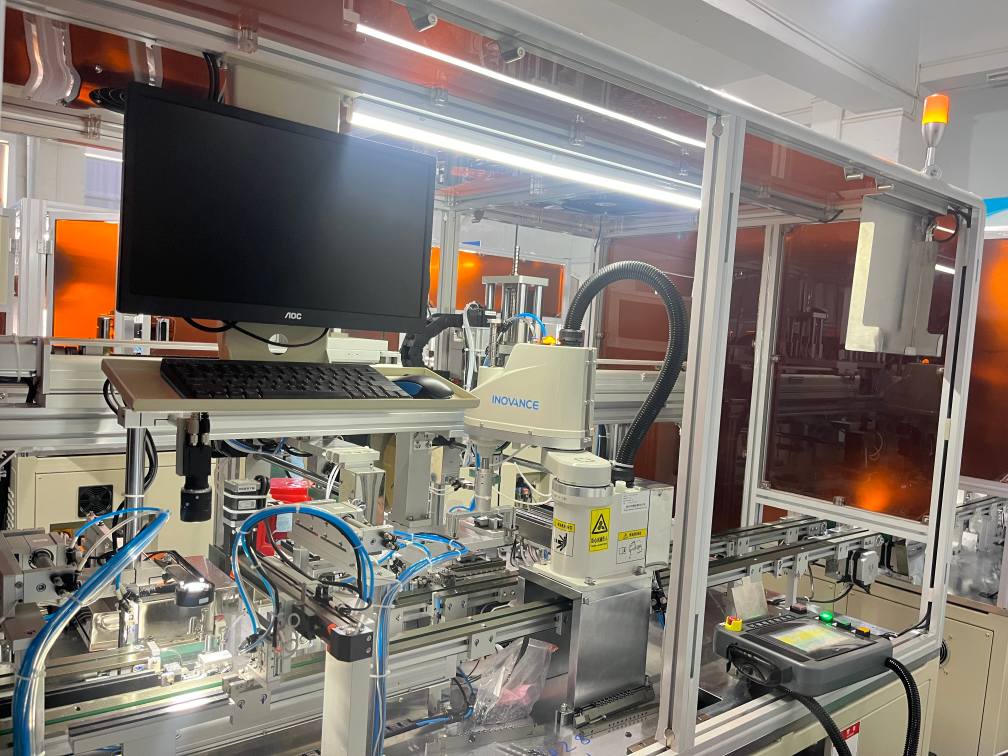
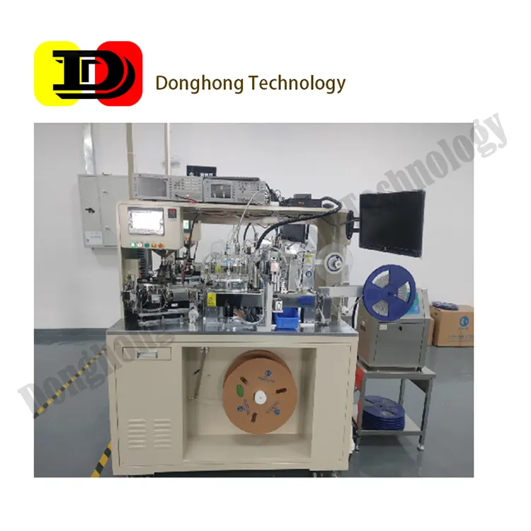
Indexing disc and tape-and-reel packaging architecture
The packaging stage converts tested parts into a reel that the customer's pick-and-place machine can consume without intervention. Two architectures dominate:
- Indexing disc type. Parts are carried around a rotating disc through test → inspection → orientation → pocket loading → taping. The disc gives a fixed cycle time per position, which makes throughput predictable and keeps each inspection station stationary. This architecture suits high-volume single-family production.
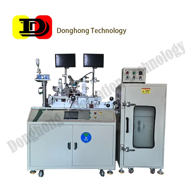
- In-line type. Parts move linearly through the stations. Changeover between part sizes is typically faster, which suits a factory running many low-volume part numbers.
Whichever architecture is chosen, four packaging parameters must be specified:
- Pocket position tolerance — the placement accuracy of the part inside the carrier tape pocket. If this exceeds the customer's feeder tolerance, the nozzle misses the part and the customer's line stops.
- Orientation consistency — for parts with a polarity or an asymmetric terminal, orientation must be verified, not assumed.
- Cover tape sealing — seal strength must be high enough to survive shipping and low enough that the customer's peeler opens it. This is a specification, not a machine default.
- Reel count accuracy — the actual quantity on the reel versus the label. Short counts are discovered at the customer's line and damage trust disproportionately to their cost.
Test and packaging specification table
| Stage | Parameter | Why it matters | How to verify on acceptance |
|---|---|---|---|
| Electrical test | Test frequency for L; full parameter set (L, DCR, Q as applicable) | Inductance is frequency dependent; partial parameter sets let defects escape | Correlation with a reference LCR meter on 30 sample parts |
| Electrical test | Test throughput vs parameter set | More parameters take longer; the line balance depends on it | Measure actual cycle time at the full parameter set |
| Visual inspection | External geometry: chipping, contamination, terminal alignment | Catches defects that would become feeder or solder failures | Known-good and known-bad sample library |
| Internal inspection | UV-IR thermal imaging for hidden cracks | Optical methods cannot see inside the core; cracks pass room-temperature electrical test | Detect rate on deliberately cracked samples |
| Packaging | Pocket position tolerance; orientation verification | Exceeding feeder tolerance stops the customer's line | Measure pocket offset across 100 consecutive pockets |
| Packaging | Cover tape seal strength; reel count accuracy | Seal failures and short counts surface at the customer | Peel force test; count verification per reel |
Acceptance checklist for a test-and-pack machine
- Does the test set cover every parameter on your finished-part datasheet?
- Is the test frequency programmable per part number, and is it recorded in the traceability data?
- Can the machine reject and segregate parts by failure mode, rather than one combined reject bin? Failure-mode segregation is what turns inspection data into process feedback.
- Is the inspection method capable of detecting internal defects, or only surface ones?
- Is pocket position tolerance specified as a number, and measured on your parts?
- Is data logging available for each part — result, parameter values, timestamp? This is what allows a customer complaint to be traced to a production window.
- Is changeover time specified for the part sizes you actually run?
If you send us your part datasheet and the feeder specification of your customer's placement equipment, we will confirm the matching test parameter set and packaging tolerances. Send an inquiry with the datasheet attached to begin.
Frequently asked questions
Why does a cracked inductor pass electrical test?
Because at room temperature the crack has not yet interrupted the current path or significantly changed the inductance. The defect only becomes electrically visible when thermal expansion during reflow or mechanical stress in service opens it further. This is why internal inspection methods such as active thermal imaging are needed in addition to electrical test.
What is the difference between passive and active thermal imaging?
Passive infrared relies on heat the part already emits, which is negligible at room temperature. Active thermal imaging excites the part first and then images the thermal response; a crack changes the local heat conduction rate, producing a detectable signature. Only the active method works for room-temperature inspection of an unpowered component.
Should testing happen before or after taping?
Electrical test and inspection should happen before pocket loading, so that rejected parts never enter the carrier tape. Testing after taping requires the machine to remove and replace a part inside a sealed pocket, which adds a failure mode for no benefit.
How is test frequency chosen?
It should match the frequency at which the customer specifies or measures the part. Power inductors are commonly specified at 100 kHz or 1 MHz; RF and high-frequency ceramic parts are specified higher. Testing at a frequency different from the datasheet produces a number that will not correlate with the customer's incoming inspection.
Can one machine handle both testing and packaging?
Yes, and integrated platforms reduce handling. The trade-off is changeover time and the cost of a stoppage: if the tester and the packager are one unit, a fault stops both functions. For high-mix production, some factories deliberately keep them separate. Specify which model fits your mix before ordering.
Dongguan Donghong Automation Technology Co., Ltd. manufactures testing and packaging machines, visual inspection stations and complete inductor automation lines from its 5,000 sqm facility in Dongguan, Guangdong. Established 2013, with more than 50 patents and 8 software copyrights. Contact us to review your test parameter set and packaging tolerances.