Quick answer
The short answer: SMD inductor quality is decided by three sequential processes — winding, gluing and soldering. Specify winding first (tension control and turn accuracy set the electrical baseline), then gluing (dispensing volume and positional accuracy set the mechanical baseline), and finally soldering (thermal profile and placement accuracy set the joint reliability). Buying a single machine without matching the other two is the most common cause of a line that tests well in sample runs but drifts in mass production.
Why process sequence decides yield, not individual machines
An inductor production line is a chain of tolerance handovers. The winding process produces a coil whose inductance depends on turn count and winding tension. The gluing process fixes that coil's geometry inside the core with a controlled volume of adhesive. The soldering process creates the electrical joint between the coil termination and the terminal electrode.
Each process consumes the tolerance left by the previous one. If winding leaves ±5% inductance spread, no amount of downstream precision recovers it — gluing and soldering will faithfully reproduce that spread into the finished component. This is why experienced buyers specify from the electrical parameter backwards, not from the machine catalogue forwards.
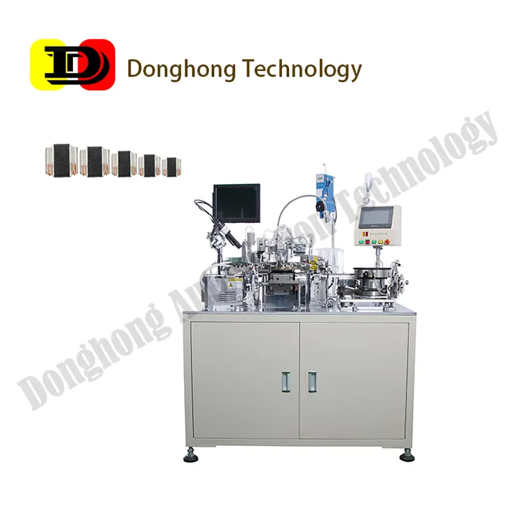
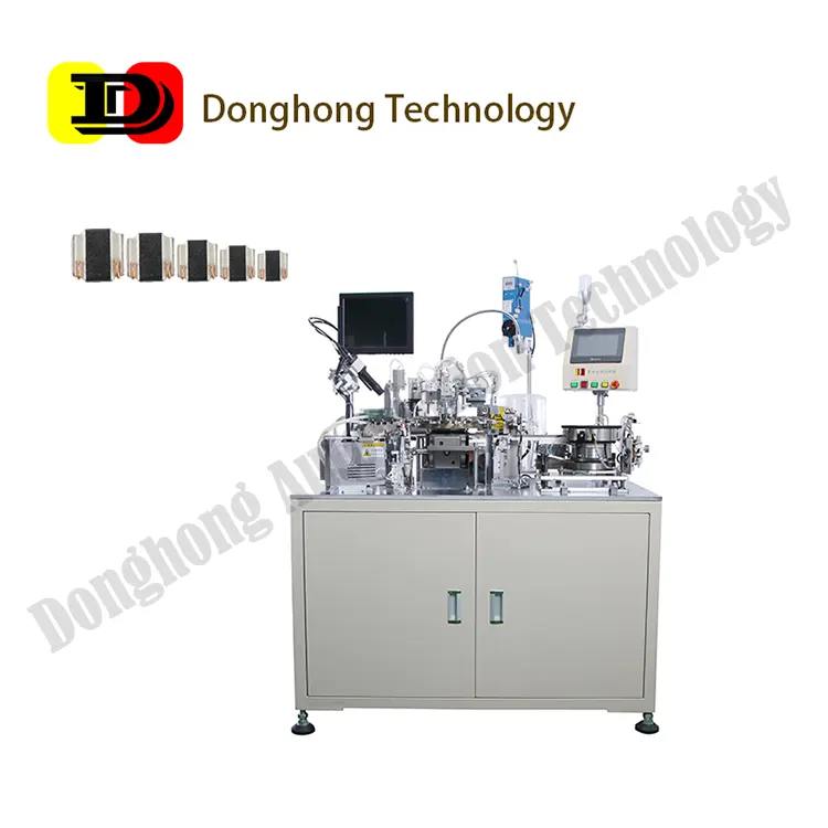
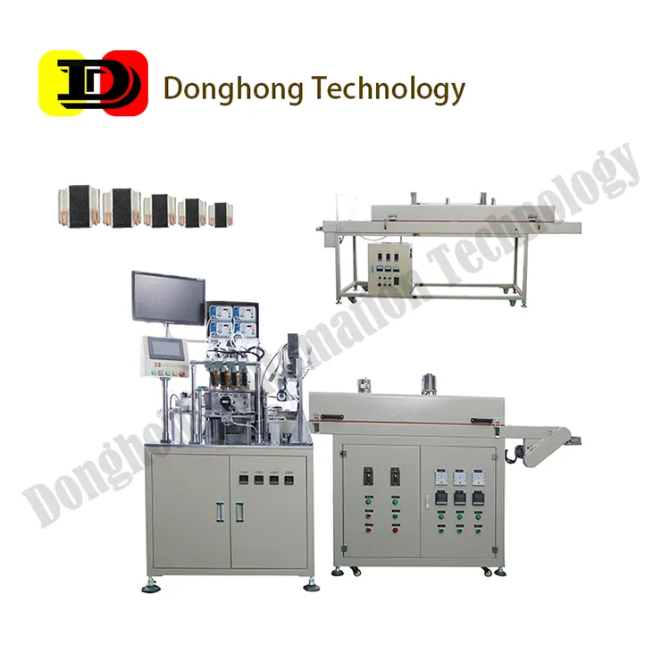
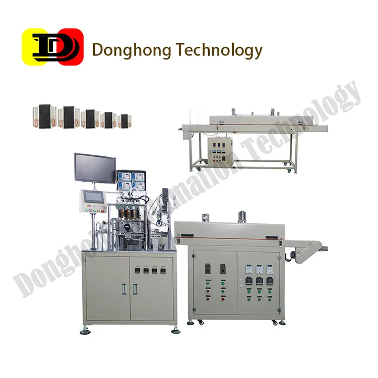
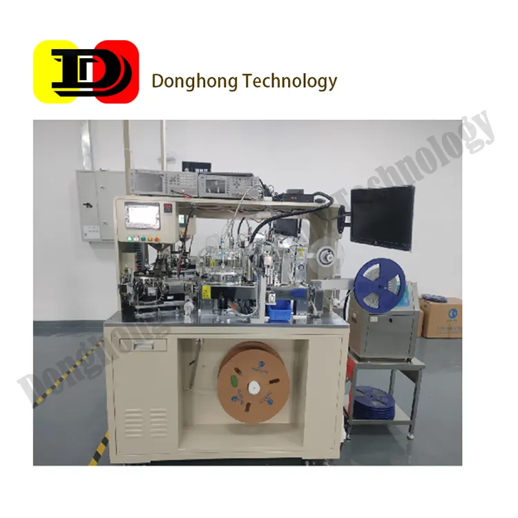
Dongguan Donghong Automation Technology has built inductor automation equipment since 2013, covering winding, dispensing, soldering, testing and packaging machines for the full range of T-Core, common mode, NR, high-frequency ceramic, molded, shielded and CD type inductors. That experience across seven inductor families is the practical basis for the selection logic below.
Process one: winding — tension, turns and wire waste
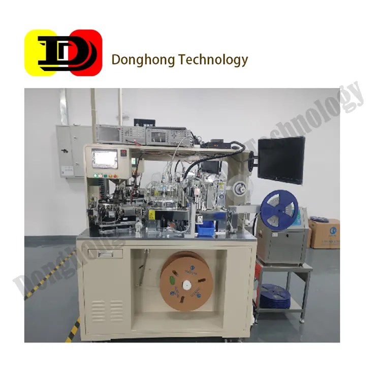
Winding is where the electrical performance is created. Three variables matter most:
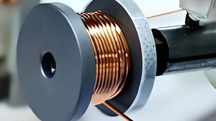
- Wire tension control. Tension that varies during a single coil changes the wire's elongation, which changes the effective cross-section and therefore the DC resistance (DCR). Servo-based closed-loop tension control holds the target force throughout the acceleration and deceleration phases of each turn.
- Turn count and layering. For multi-layer windings, the transition point between layers must be controlled so that the wire does not cross over itself. Crossing produces a localised bulge that later interferes with the core cavity during gluing.
- Wire waste. Every start and end of a coil produces scrap. Automatic lead handling (cutting, clamping and positioning) is what separates a machine that wastes 5% of copper from one that wastes under 2%.
AI visual inspection integrated into the winding machine now catches wire-crossing and missing-turn defects at the coil stage, rather than discovering them after encapsulation when the part is already scrapped. For NR magnetic adhesive inductors, the winding machine is typically paired with a winding-and-gluing integrated unit so the coil is fixed before it can relax.
Process two: gluing — dispensing volume and multi-axis synchronisation
Gluing converts a loose coil into a dimensionally stable component. It is the process most often underestimated at the specification stage, because adhesive behaviour is not visible in the finished part.
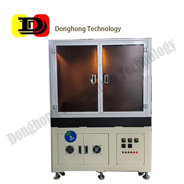
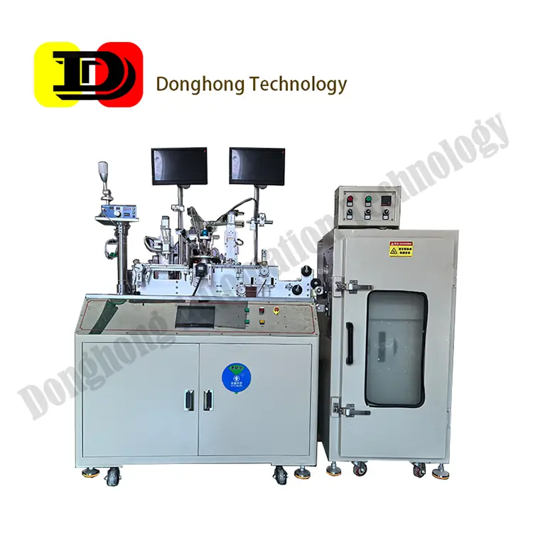
- Dispensing volume repeatability. Under-filling leaves the coil free to move under thermal cycling; over-filling bleeds adhesive onto the terminal area and causes soldering defects later. Volumetric or time-pressure dispensing with closed-loop compensation holds volume across a shift.
- Positional accuracy. The nozzle must reach a repeatable XY position relative to each cavity. Multi-axis configurations allow several dispensing heads to work in parallel, which is what makes the process economical at high output.
- Synchronisation with baking. Adhesive cure begins as soon as the part is dispensed. If the transfer from dispenser to oven is not synchronised, cure state varies part to part — and cure state affects the final inductance value.
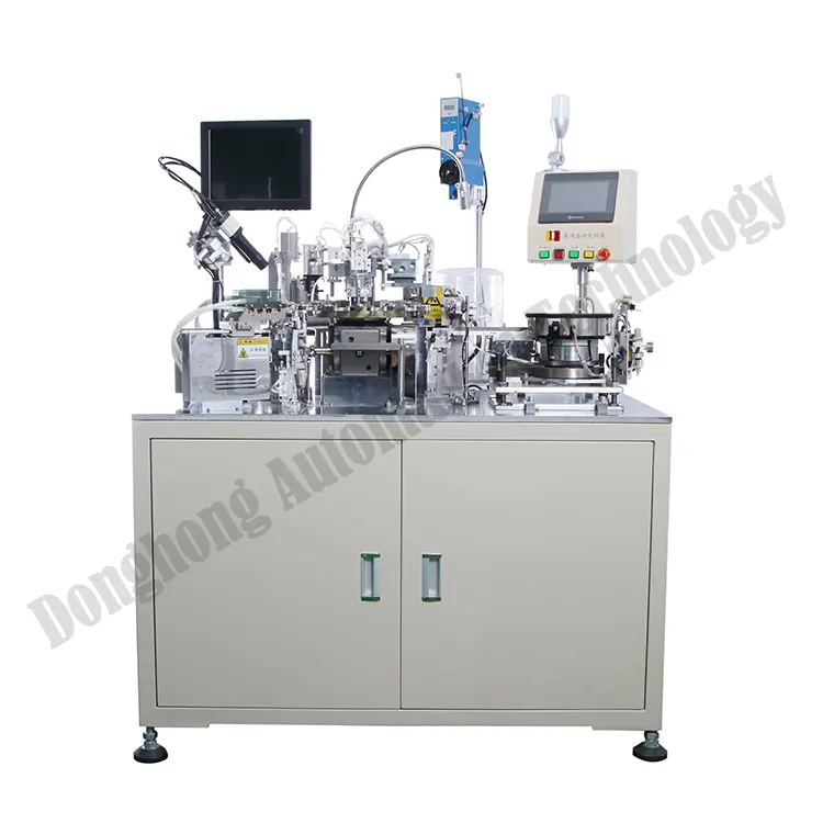
Bus-based control of multiple axes allows dispensing, transfer and baking to run as one unmanned sequence. This is the architectural difference between a standalone dispensing machine and a gluing machine that can be dropped into an existing line without adding an operator.
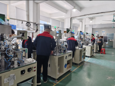
Process three: soldering — thermal profile and placement accuracy
Soldering creates the electrical joint and is where latent defects enter the finished inductor. Two specification points dominate:
- Thermal profile control. The solder joint must reach wetting temperature without overheating the magnetic core or the adhesive. Robotic soldering with closed-loop temperature control applies energy only where the joint is, rather than heating the whole part in a wave or reflow batch.
- Placement accuracy. For miniaturised inductors and magnetic adhesive components, the terminal and the coil lead are close together. Positioning error of a few tenths of a millimetre produces a cold joint that passes in-circuit test but fails after thermal cycling.
Robotic soldering stations handle the terminal-common-mode, NR and CD families with the same platform, which simplifies spare-part management across a multi-family factory. For high-reliability applications — automotive power supplies, fast-charging modules, communication base stations — the soldering profile is not a cost item but a reliability requirement.
The three-process comparison table
| Process | Controls | Key specification | Typical failure if under-specified | Inspection point |
|---|---|---|---|---|
| Winding | Inductance, DCR, Q value | Tension control type (servo closed-loop vs mechanical); turns programming resolution | Wide inductance spread; high copper scrap rate | Turn count and wire-crossing, in-process |
| Gluing | Mechanical stability, thermal cycling life | Dispensing volume repeatability; number of synchronised axes; cure-transfer synchronisation | Coil movement under heat; adhesive bleed onto terminals | Dispensed weight sample, per shift |
| Soldering | Joint reliability, contact resistance | Thermal profile control; placement accuracy (mm); heating method | Cold joints that pass test but fail in field | Pull test plus visual/AOI |
Handover tolerances between processes
The specification conversation should be about the tolerance budget, not about individual machine accuracy figures. A practical way to set it:
- Start from the finished part specification — inductance tolerance and DCR tolerance the customer's design requires.
- Allocate roughly half of that budget to winding, because winding is the dominant contributor.
- Allocate the remaining half across gluing (geometry shift) and soldering (joint resistance).
- Verify that the machines you are considering can each hold their allocated share, measured on your own parts — not on the vendor's demo parts.
This is also why process selection should be done as a set. A buyer who specifies a high-accuracy winding machine and then chooses the lowest-cost dispensing machine has simply moved the bottleneck downstream, and will discover it during mass production rather than during sampling.
Specification checklist before you order
- Which inductor families must the line handle — NR, T-Core, CD, shielded, common mode, high-frequency ceramic, molded? A single-family line can be simpler; a multi-family line needs changeover time specified.
- What is the target output per hour, and at what cavity count? Output claims must state the cavity count they were measured at.
- What is the required inductance tolerance? This sets the winding tension-control requirement.
- Is dispensing-to-baking transfer automatic, and is it synchronised?
- What is the soldering method, and can the thermal profile be programmed per part number?
- Are winding, gluing and soldering available from one supplier, so the tolerance handover is a single responsibility?
- Is AI visual inspection available in-process, or is inspection only at final test?
If you send us your finished-part specification and target output, our engineers will map it against the winding, gluing and soldering platforms and return a process recommendation with the tolerance allocation made explicit. Send an inquiry to start that review.
Frequently asked questions
Which process should I automate first if I can only buy one machine?
Winding, in almost every case. Winding sets the electrical parameters, so automating it delivers the largest reduction in spread and scrap. Automating gluing or soldering first improves labour cost but leaves the dominant tolerance source manual.
Can one machine handle both NR and T-Core inductors?
Some winding platforms can, via program change and fixture change. The practical constraint is not the winding motion but the material handling — NR magnetic adhesive parts and T-Core parts differ in how they are fed, oriented and gripped. Specify changeover time explicitly if multi-family flexibility is a requirement.
How do I verify the dispensing volume claim?
Ask for a dispensed-weight study on your own adhesive, not the vendor's reference adhesive. Adhesive viscosity, temperature and pot life all affect volume, so a demonstration with a different material does not transfer. Weigh 30 consecutive parts and check the standard deviation, not just the mean.
Is AI visual inspection a replacement for final electrical test?
No. Visual inspection catches geometric defects — wire crossing, missing turns, cracks, contamination — that would become electrical failures later. Final electrical test measures inductance, DCR and Q. The two are complementary: visual inspection prevents you from paying for the downstream processing of a part that is already defective.
What is the advantage of robotic soldering over wave soldering for inductors?
Localised heating. Robotic soldering brings energy to the joint rather than immersing the whole part in a thermal bath, which matters when the magnetic core or the adhesive has a lower thermal limit than the solder alloy requires. It also removes the need for a masking step on parts where the terminal geometry is exposed.
Dongguan Donghong Automation Technology Co., Ltd. has manufactured inductor automation equipment since 2013 from a 5,000 sqm facility in Dongguan, Guangdong, with more than 50 patents and 8 software copyrights. Products cover winding, gluing, soldering, testing and packaging machines for T-Core, common mode, NR, high-frequency ceramic, molded, shielded and CD inductors. Contact us for a process specification review.