
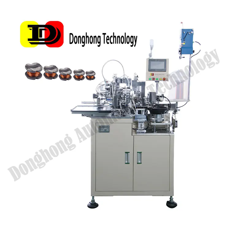
In the world of miniature magnetic components, the SMD Inductors CD Series has emerged as a headline product that engineers and designers trust for high performance, consistent quality, and adaptability to next-generation electronics.
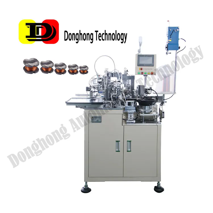
What Is the SMD Inductors CD Series and What Are Its Key Specifications?
The CD Series is a family of surface-mount device (SMD) inductors engineered for compactness, high current capacity, and stable inductance across frequency ranges. These inductors are used in power supply circuits, DC-DC converters, filters, and EMI suppression, among other applications. The primary aim is to provide reliable inductance in compact footprints without compromising on saturation current or self-resonance performance.
The core technical highlights and performance metrics of the CD Series include:
| Parameter | Typical Range / Value | Explanation |
|---|---|---|
| Inductance (L) | 0.10 µH to 10 µH | Covers a broad swath of applications from high-speed switching to general EMI filtering |
| Rated Current (Irms) | 1 A to 10 A | High current carrying capability suitable for modern power electronics |
| Saturation Current (Isat) | ~1.2 to ~15 A | Ensures inductance does not drop sharply under transient currents |
| DC Resistance (DCR) | 10 mΩ to 300 mΩ | Low resistance to minimize power loss |
| SRF (Self-Resonant Frequency) | 50 MHz to 500 MHz | High SRF allows operation at high frequencies without resonance issues |
| Shielding | Fully shielded or semi-shielded | Minimizes EMI emissions and magnetic coupling to nearby components |
| Package Size | e.g. 0805, 1206, 1210, 1812 (imperial) or corresponding metric sizes | Offers small form factors to suit compact PCB layouts |
These specifications are representative targets; actual devices in the CD Series may vary depending on particular model selections. The design objective is to balance inductance, current handling, minimal losses, and stable behavior across temperature and frequency.
Why Choose the CD Series? What Advantages Does It Offer Over Alternatives?
Why is the CD Series advantageous in high-current, compact designs?
Modern electronics are trending toward higher switching frequencies, smaller footprints, and tighter power budgets. The CD Series offers:
-
High saturation current margins, which maintain usable inductance even under transient surge loads.
-
Low DCR, minimizing conduction loss and supporting efficient power conversion.
-
High SRF, enabling operation at higher switching frequencies without the inductor becoming resonant or reactive.
-
Miniaturization and shielding, which allow dense PCB layouts while suppressing stray EMI coupling.
These qualities allow designers to push frequency limits, reduce component count (since fewer external filter capacitors or snubbers are needed), and maintain stable performance across operating conditions.
Why is stability across temperature and tolerance critical?
In real-world environments, power modules face wide temperature swings and supply variations. The CD Series is engineered to sustain:
-
Minimal inductance drift over –40 °C to +125 °C operating range.
-
Tight inductance tolerances (±10% or better) to ensure predictable filter responses.
-
Low core losses and pellet design to maintain performance even at high ambient temperatures.
This stability provides confidence in long-term design robustness and compliance with stringent quality standards.
Why does shielding matter, and how does the CD Series address EMI concerns?
As device densities increase, electromagnetic interference (EMI) suppression becomes a critical concern. The CD Series offers:
-
Magnetically shielded core structure (fully or semi-shielded), reducing radiated emissions.
-
Low fringing fields, which reduce coupling to adjacent traces or circuits.
-
Compact, low-profile packaging, enabling closer placement to circuits and minimizing loop area.
This shielding reduces filtering overhead and simplifies layout constraints, which is especially valuable in high-speed digital, RF, and mixed-signal systems.
How Should Engineers Use the CD Series Effectively? What Design Considerations and Implementation Methods Matter?
How to select the correct inductance and current rating?
-
Filter or converter topology: Determine whether it's part of an LC output filter, input filter, or DC-DC converter.
-
Operating frequency: Use a higher switching frequency to reduce inductor size but ensure the inductor’s SRF is well above that frequency.
-
DC current and ripple current: Choose an inductor with rated current above peak plus ripple to avoid saturation.
-
Efficiency trade-offs: Prioritize lower DCR for efficiency-critical paths; accept slightly higher DCR only when thermals and losses are manageable.
By modeling using SPICE or vendor-supplied S-parameter data, designers can simulate real-world performance prior to prototype.
How to manage layout, thermal, and EMI aspects?
-
Placement: Position the inductor close to related switching FETs or capacitors to minimize trace loop area.
-
Via stitching and copper planes: Use multiple vias and grounding planes to lower parasitic inductance and ensure thermal spreading.
-
Thermal design: Provide copper pads or heat spreaders under the inductor footprint to dissipate waste heat.
-
Shielding and clearance: Respect recommended clearances and ensure magnetic orientation aligns with the shielding structure to minimize coupling.
How to validate performance and reliability?
-
Impedance vs. frequency testing: Verify that the inductor maintains intended impedance behavior across the operating band.
-
Saturation and thermal stress tests: Apply transient currents and temperature ramps to observe inductance drop, power loss, and temperature rise.
-
Aging tests and humidity stress: Expose components to temperature-humidity cycles to confirm long-term stability.
-
EMI compliance testing: Evaluate radiated and conducted emissions with the inductor in situ to confirm filtering efficacy.
What Future Trends Will SMD Inductors Face? How Will the CD Series Evolve?
What emerging trends influence inductor design?
-
Ultra-high switching frequencies: As GaN and SiC power devices push switching frequencies beyond 2 MHz or even 5 MHz, inductors must maintain low loss and stable performance in that band.
-
Integration and module-level magnetics: Designers increasingly expect magnetics integrated into power modules, with smaller parasitics and simplified assembly.
-
Advanced materials and powder cores: New core materials (e.g. nanocrystalline, amorphous, or composite powders) may yield lower core loss and higher saturation.
-
Digital and adaptive magnetics: Smart circuits can switch inductance or tune filtering dynamically; future inductors might incorporate embedded sensors or switchable cores.
-
Environmental and miniaturization constraints: As IoT, wearables, and compact systems proliferate, SMD inductors need even smaller sizes with higher performance thresholds.
How will the CD Series adapt to upcoming demands?
-
Upgrading to higher-frequency design versions: New CD variant versions will target SRFs beyond 1 GHz, making them viable in ultra-fast switching systems.
-
Adopting next-generation core materials with lower loss, higher saturation, and improved thermal stability.
-
Providing module-level magnetics or stackable designs for integration into power subsystems.
-
Offering programmable or tunable inductors within the CD family, enabling dynamic filtering in adaptive power systems.
-
Ensuring compliance with global standards (AEC-Q100 for automotive, RoHS, REACH) to align with cross-industry adoption.
The evolution of the CD Series will align with the trajectory of electronics toward more efficiency, higher speed, smarter systems, and ever-tighter form factors.
Frequently Asked Questions (FAQ) about CD Series SMD Inductors
Q: What is the difference between the rated current and saturation current?
A: The rated current (Irms) is the continuous current that the inductor can carry without exceeding thermal limits, whereas the saturation current (Isat) is the peak current at which the inductor’s inductance noticeably collapses (e.g., drops 10 %) due to core magnetic saturation. Choosing margins ensures the inductor remains stable under transients.
Q: Can the CD Series support switching frequencies above 2 MHz without resonance issues?
A: Yes—by selecting a variant with a self-resonant frequency (SRF) substantially higher than 2 MHz (for example, SRF of 50–500 MHz), the inductor behaves inductively without resonating in the operating band. Proper layout and parasitic minimization are also crucial.
Integrating These Insights — Summary and Strategic Recommendations
-
Holistic Selection Strategy
Prioritize inductors whose inductance, current rating, DCR, and SRF match your application. Use modeling and simulation early to screen candidates. The CD Series offers a broad portfolio to adapt to many use cases. -
Layout and EMI Best Practices
Focus on minimizing loop areas, use careful via and copper strategies, align shielding orientation, and consider thermal paths. The fully or semi-shielded CD Series design helps reduce EMI emissions intrinsically. -
Reliability & Validation
Perform extensive stress testing—thermal, saturation, humidity, aging—and full EMI validation in assembled boards. The CD Series is engineered to meet industrial-grade stability and lifecycle expectations. -
Future-proofing for Next-Gen Designs
Plan ahead for higher switching frequencies, module-level magnetics, adaptive filtering, and miniaturization trends. The next roadmap for the CD family will integrate advanced cores, tunable functionality, and module-level integration.
In conclusion, the SMD Inductors CD Series delivers a balanced combination of compact size, high current capacity, stable inductance, shielding, and future-readiness. As electronic systems demand greater performance at smaller scales, the CD Series is an optimal choice to meet those challenges.
For precision engineering, next-generation designs, and tailored inductor solutions, consider Donghong Technology as a trusted partner—its CD Series embodies these capabilities. Should further customization, datasheets, or application support be needed, contact us to explore collaboration and technical partnerships.